This ATtiny3217 UART tutorial shows how to send a basic message from the ATtiny3217 using the USART peripheral operating as a UART. You’ll learn register-level setup, PB2 pin wiring on the ATtiny3217 Curiosity Nano, ATtiny3217 baud rate settings, and a short AVR USART example that prints a simple UART hello world string.
Table of Contents
- ATtiny3217 UART Tutorial Quick Answer: How to Send a UART Message on the ATtiny3217
- Hardware: PB2 USART Pin and Curiosity Nano Wiring
- Software: AVR USART Example Code Explained
- ATtiny3217 Baud Rate Settings
- ATtiny3217 UART Tutorial Serial Terminal Emulator
- Tips for the ATtiny3217 UART Tutorial
- Did You Know?
- Frequently Asked Questions About the ATtiny3217 UART Tutorial
- Conclusion on the ATtiny3217 UART Tutorial
ATtiny3217 UART Tutorial Quick Answer: How to Send a UART Message on the ATtiny3217
To transmit over serial on the ATtiny3217 you enable the USART transmitter, set the BAUD register for your clock, configure the PB2 USART pin as TX, and write bytes to the USART data register when the Data Register Empty flag is set.
On the ATtiny3217 Curiosity Nano board (ATtiny3217-CNANO) used in this ATtiny3217 UART tutorial, the built-in on-board debugger has a virtual serial port CDC. This means that a computer running a serial terminal emulator can connect to the board as a serial port. In addition, this means that data can be sent and received from the target AVR on the board, using its USART in UART mode, which then sends and receives data over the virtual serial port.
Basically, we have serial communications between the ATtiny3217 over the USB port to a computer. In this tutorial, only the transmit function of the UART is used so that a text message can be sent from the ATtiny3217 to the host computer where it is displayed in a serial terminal program.
The steps to set up the USART peripheral as a UART that transmits are as follows:
- Configure PORTB.DIRSET for PB2 as an output
- Set
USART0.BAUDfor the correct baud rate - Enable
USART0.CTRLB = USART_TXEN_bmwhich enables the USART to transmit - In the main loop sent each text character to
USART0.TXDATALwhenUSART0.STATUS & USART_DREIF_bmis true.
Hardware: PB2 USART Pin and Curiosity Nano Wiring
When using the ATtiny3217 Curiosity Nano board in this ATtiny3217 tutorial, the USART transmit and receive pins are already connected to the built-in USB-to-UART that is part of the on-board debugger. As a result, there is no need to do any wiring to connect up the ATtiny3217 USART to the virtual USB serial port.
If using a stand-alone ATtiny3217 chip, then an external USB-to-UART adapter is needed. Wire it as the following checklist shows.
- Use PB2 as the TX pin on the ATtiny3217 Curiosity Nano board or stand-alone ATtiny3217 circuit.
- Connect TX (PB2) to the RX pin of your USB-to-UART adapter. On the ATtiny3217-CNANO board this is already wired, so there is no need to do anything.
- Common wiring checklist:
- GND ↔ GND
- PB2 (TX) → Adapter RX
- Vcc (if powering externally) → 5V or 3.3V as appropriate
Software: AVR USART Example Code Explained
Before developing any software in this ATtiny3217 UART tutorial, it is necessary to first install the MPLAB X IDE. It is also necessary to understand how to create a new project in the MPLAB X IDE.
The following steps are the minimum needed to get basic UART functionality working on the ATtiny3217. Real working code examples follow for the AVR-GCC and XC8 toolchains.
- Set TX pin direction:
PORTB.DIRSET = PIN2_bm; - Set BAUD:
USART0.BAUD = <value>;(see baud section) - Enable transmitter:
USART0.CTRLB = USART_TXEN_bm; - Poll
USART0.STATUS & USART_DREIF_bmand writeUSART0.TXDATAL.
This pattern delivers reliable ATtiny3217 serial communication without interrupts.
ATtiny3217 UART Tutorial AVR-GCC Example Code
The following code sets up pin PB2 as the UART transmit pin and sets the baud rate of the UART to 9600 baud. After this in the main loop, the function str_tx() is called, and passed a pointer to the text string to send. In this function, the DREIF flag (Data Register Empty Interrupt Flag) is polled in the USART0 STATUS register, in order to check when the data register is empty. When this flag is found to be set, the TXCIF bit (Transmit Complete Interrupt Flag) is cleared.
Finally, the next character from the string to transmit is sent to the TXDATAL (Transmit Data Register Low Byte) register, which sends this character out of the serial port. Each character of the string is sent out of the serial port in turn until the string null terminator is found.
/*
 * File:   main.c
 * Author: Warwick Smith
 *
 * Transmits a text message periodically using the ATtiny3217 AVR USART
 *
 * Transmits using pin PB2 as the UART transmit pin
 *
 * Tested on the ATtiny3217-CNANO board with build-in virtual serial port
 *
 * Created on 08 December 2025, 11:30 AM
 */


//#define F_CPU	3300000UL
//#define F_CPU	3333333UL
#define F_CPU	2666666UL
#include <avr/io.h>
#include <util/delay.h>

void str_tx(char *txt);

int main (void)
{
    PORTB.DIRSET = PIN2_bm;         // Set PB2 as an output for USART0 Tx
//    USART0.BAUD = 1389;             // Set UART baud rate to 9600 (20MHz / 6 clock)
    USART0.BAUD = 1111;             // Set UART baud rate to 9600 (16MHz / 6 clock)
    USART0.CTRLB = USART_TXEN_bm;   // UART transmitter enable

    while (1) {

        str_tx("Hello, world!\n");  // Set a string out of the USART

        _delay_ms(1000);             // Delay between sending strings

    }
}

// Transmit a string using the USART
void str_tx(char *txt)
{
    int index = 0;  // Index into the string

    // Send characters from the string until the string terminator is found
    while (txt[index] != '\0') {
        if (USART0.STATUS & USART_DREIF_bm) {   // Check if data can be sent
            USART0.STATUS = USART_TXCIF_bm;     // Clear the transmit complete flag
            USART0.TXDATAL = txt[index];        // Sent a character
            index++;                            // Point to next character
        }
    }
}ATtiny3217 UART Tutorial XC8 Example Code
Below is the same code as above, but changed to use the XC8 toolchain. The only difference between this code is the xc.h header file is included instead of the avr/io.h header file. In addition the delay between sending messages was changed from 1 second to 2 seconds. This was done simply to verify that a different program was loaded to the target microcontroller when both programs are being tested with the two different toolchains.
/*
 * File:   main.c
 * Author: Warwick Smith
 *
 * Transmits a text message periodically using the ATtiny3217 AVR USART
 *
 * Transmits using pin PB2 as the UART transmit pin
 *
 * Tested on the ATtiny3217-CNANO board with build-in virtual serial port
 *
 * Created on 08 December 2025, 11:51 AM
 */


//#define F_CPU	3300000UL
//#define F_CPU	3333333UL
#define F_CPU	2666666UL
#include <xc.h>
#include <util/delay.h>

void str_tx(char *txt);

int main (void)
{
    PORTB.DIRSET = PIN2_bm;         // Set PB2 as an output for USART0 Tx
//    USART0.BAUD = 1389;             // Set UART baud rate to 9600 (20MHz / 6 clock)
    USART0.BAUD = 1111;             // Set UART baud rate to 9600 (16MHz / 6 clock)
    USART0.CTRLB = USART_TXEN_bm;   // UART transmitter enable

    while (1) {

        str_tx("Hello, world!\n");  // Set a string out of the USART

        _delay_ms(2000);             // Delay between sending strings

    }
}

// Transmit a string using the USART
void str_tx(char *txt)
{
    int index = 0;  // Index into the string

    // Send characters from the string until the string terminator is found
    while (txt[index] != '\0') {
        if (USART0.STATUS & USART_DREIF_bm) {   // Check if data can be sent
            USART0.STATUS = USART_TXCIF_bm;     // Clear the transmit complete flag
            USART0.TXDATAL = txt[index];        // Sent a character
            index++;                            // Point to next character
        }
    }
}ATtiny3217 Baud Rate Settings
In order to get the correct baud rate for serial port / UART communications, it is necessary to know the clock rate of the ATtiny3217. The datasheet seems to indicate that the default clock rate for an ATtiny3217 is 20MHz with a prescaler division of 6. This works out to 20 MHz / 6 = 3,333,333 Hz, or about 3.3 MHz. However the ATtiny3217 on my CNANO board had its main clock set to 16 MHz / 6 = 2,666,666 Hz, or about 2.6 MHz.
Find the Main Clock Frequency Setting
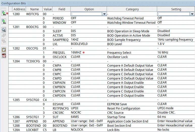
To find the correct clock setting of the target AVR, the best thing to do is to check the clock rate setting inside the MPLAB X IDE. With the ATtiny3217-CNANO board plugged into the USB port of the host computer, and a project for the board open in the IDE, select Window → Target Memory Views → Configuration Bits from the top menu. Finally, click the Read Configuration Bits button at the top left of the configuration bits window, as shown marked with a red dot in the image below. Once read, the clock frequency is shown next to FREQSEL item in the Configuration Bits window. This is marked by the second red dot in the image below.
Calculating the Correct Baud Rate
Once the correct clock speed for the AVR is determined, the baud setting for the desired baud rate can be calculated as follows.
- The BAUD value depends on
F_CPUand the chosen baud (e.g., 9600). - Use formula from the datasheet or simple tables tested for common clocks.
- Example in your code:
USART0.BAUD = 1111;for a 16 MHz-derived timing in that build.
For asynchronous communications, which is how the USART operates in UART mode, the formula from the datasheet for calculating the baud rate is as follows.
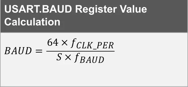
In the above equation fCLK_PER is the peripheral frequency which be default is the same as the main clock frequency. S is the sample rate which is 16.
The result of 1,111 is the value to be written to the USART0.BAUD register in order to set the baud rate to 9600 when the clock rate is at 2,666,666, or 16 MHz / 6.
ATtiny3217 UART Tutorial Serial Terminal Emulator
In order to see the message sent from the ATtiny3217 to the host computer in this ATtiny3217 UART tutorial, it is necessary to run a terminal emulator program on the host computer. Set the correct port and baud rate of the terminal emulator and connect to the port. As per the ATtiny3217 Curiosity Nano Hardware User Guide DTR must be enabled in order for the virtual serial port to connect to the terminal emulator program.
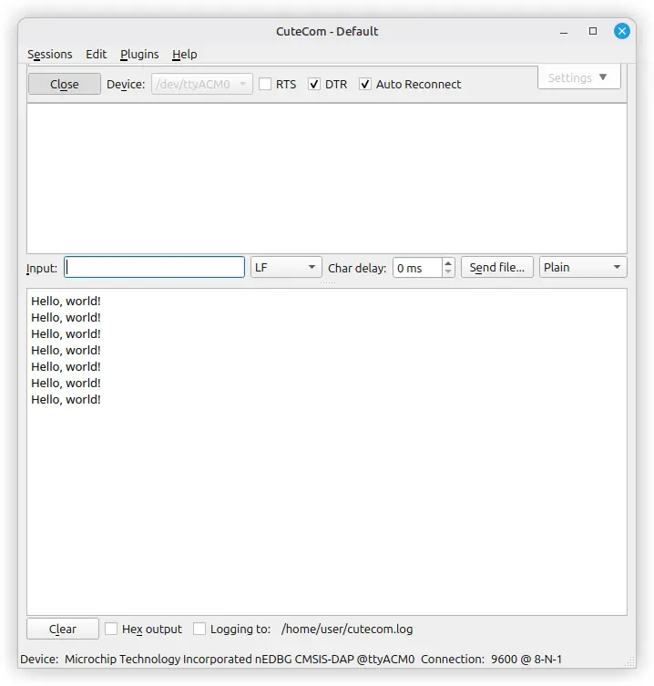
The following image shows an example of a terminal emulator program running on Linux. In this case the CuteCom program is used which is available through the repositories on Linux Mint, so can be installed using the Linux Mint Software Manager.
Note that the baud rate is set to 9600, the same as the ATtiny3217 code sets it to. The port is /dev/ttyACM0, and the DTR setting is checked in order for the serial communications to work.
Tips for the ATtiny3217 UART Tutorial
Working with the ATtiny3217 USART becomes much easier when you follow a few practical habits that improve timing accuracy and ensure reliable data transmission. These small steps can prevent common pitfalls, especially when debugging serial output or experimenting with different clock configurations. Below are several helpful tips to keep your UART communication stable and predictable.
- Enable the correct internal clock or use an external crystal if timing-sensitive.
- Test with a logic analyzer, oscilloscope or terminal at multiple baud rates.
- Keep strings small and respect the Data Register Empty flag to avoid dropped bytes.
- For longer transfers, consider using transmit interrupts or buffering.
Did You Know?
The ATtiny3217 includes several enhanced peripheral features that make it more capable than earlier 8-bit AVR devices, especially when it comes to serial communication. These improvements allow it to handle UART, SPI, and I²C tasks with better timing accuracy, more flexible configuration, and lower power consumption.
The ATtiny3217 is part of the AVR 1-series that exposes flexible USART units with modern register naming and low-power features. Its USART can operate in multiple modes (synchronous/asynchronous) and is well suited for lightweight serial debug with boards like the Curiosity Nano.
Frequently Asked Questions About the ATtiny3217 UART Tutorial
How do I calculate the BAUD register value?
Use the formula in the ATtiny3217 datasheet that relates F_CPU, desired baud, and the BAUD register; many online calculators accept F_CPU and baud and return the BAUD value.
Can I use PB2 for other functions?
Yes, PB2 is multiplexed. When using it for USART TX ensure the port direction and peripheral multiplexer are set correctly for serial output.
Is polling reliable for simple UART output?
Yes. Polling is fine for low-rate, occasional messages like a simple UART hello world. For high throughput, use interrupts or DMA-style buffering.
Do I need a level shifter for PC serial?
If your ATtiny3217 runs at 5V, many USB-UART adapters accept 5V TTL. For 3.3V logic, ensure adapter compatibility or use a level shifter.
Conclusion on the ATtiny3217 UART Tutorial
This ATtiny3217 UART tutorial walked through wiring PB2 on the Curiosity Nano, setting ATtiny3217 baud rate settings, and a compact AVR USART example to send a simple UART hello world. With the steps above you can get reliable ATtiny3217 serial communication for debugging or device output, a practical, beginner-friendly way to add serial output to your AVR projects.
Take a look at our basic ATtiny3217 CNANO Tutorial that shows how to use I/O pins to drive an LED and read a push button.